Astable Multivibrator
Description
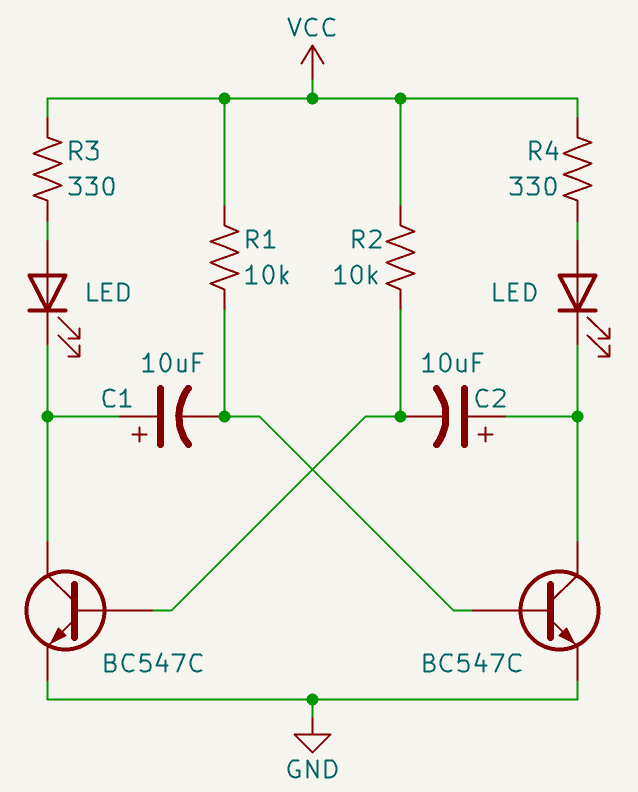
This project is a two-transistor astable multivibrator built with two BC547C NPN transistors, two LEDs, two capacitors, and a few resistors. The circuit automatically switches the two LEDs on and off alternately, creating a simple flashing light effect without using Arduino or any microcontroller. The two transistors continuously turn each other on and off through the cross-connected capacitors, producing a self-oscillating circuit. This project is useful for learning transistor switching, capacitor charging and discharging, feedback, timing networks, and the basic working principle of an astable oscillator.
Required components:
- 2x Transistor BC547C (or other suitable NPNs such as 2N2222)
- 2x 10kΩ resistor
- 2x 330Ω resistor
- 2x 10uF capacitor
- 2x LED
Schematic:
Power the circuit with a voltage of 5 to 12 V DC
How it works:
This circuit is a classic astable multivibrator. The word astable means that the circuit has no permanent stable state. Instead, it continuously changes between two temporary states: first one LED is on and the other is off, then they swap.
The two BC547C transistors work as electronic switches. Their emitters are connected to GND, their collectors are connected to the LEDs, and their bases receive control signals through the timing network.
Each LED has a 330 ohm resistor in series with it. These resistors limit the current flowing through the LEDs and protect both the LEDs and the transistors.
When one transistor turns on, current flows from VCC, through the 330 ohm resistor, through the LED, through the transistor collector-emitter path, and finally to ground. This makes that LED turn on.
When that transistor turns off, the current path is interrupted, so the corresponding LED turns off.
The two 10k resistors connect the transistor bases to VCC. Their job is to slowly charge the capacitors and provide base current to the transistors. Without these resistors, the transistors would not receive the correct bias to restart the switching cycle.
The two 10uF capacitors are cross-connected between the collector of one transistor and the base of the opposite transistor. This cross-coupling is the most important part of the circuit, because it makes each transistor affect the other one.
When power is applied, both sides are almost symmetrical, but due to tiny real-world differences one transistor turns on slightly faster than the other. For example, if the left transistor turns on first, the left LED turns on and the left collector voltage quickly drops toward ground.
This sudden voltage drop is transferred through the capacitor connected to the opposite base. As a result, the right transistor base is pulled low, keeping the right transistor off. Therefore, while the left LED is on, the right LED is off.
After that, the capacitor connected to the right transistor base begins charging slowly through its 10k resistor. As the capacitor charges, the voltage on the right transistor base gradually rises.
When the right base voltage becomes high enough, usually around 0.6V to 0.7V for a silicon transistor, the right transistor starts conducting. The right LED turns on, and the right collector voltage suddenly drops.
This sudden drop is transferred through the other capacitor to the left transistor base, pulling it low and turning the left transistor off. Now the right LED is on and the left LED is off.
The same process then repeats in the opposite direction. The capacitor on the left base slowly charges through its 10k resistor until the left transistor turns on again, switching the circuit back to the first state.
The flashing speed is mainly determined by the 10k resistors and the 10uF capacitors. Larger capacitors or larger base resistors make the charging process slower, so the LEDs blink more slowly. Smaller capacitors or smaller resistors make the blinking faster.
In this circuit, both sides use the same values, so the two LEDs should blink with approximately the same timing. However, because real components have tolerances, one side may stay on slightly longer than the other.
The electrolytic capacitors must be connected with the correct polarity. In this type of circuit, their positive sides are usually connected toward the transistor collector sides, while the other sides go toward the opposite transistor bases.
Overall, the circuit works by using two transistors that continuously disable and enable each other through capacitors. This creates an automatic alternating blink effect using only analog components.
For experimenting, the blink rate can be changed by replacing the 10k resistors with higher or lower values, or by changing the 10uF capacitors. A potentiometer can also be added to make the flashing speed adjustable.
Frequency formula:
For the symmetric circuit (the right side is equal to the left side):
\( f = \frac{1}{1.386 \, R C} \)
For the non-symmetrical circuit:
\( f = \frac{1}{0.693 \, (R_1 C_1 + R_2 C_2)} \)
In this project, the circuit is symmetrical, so the first formula must be used to calculate the frequency.Square wave image:
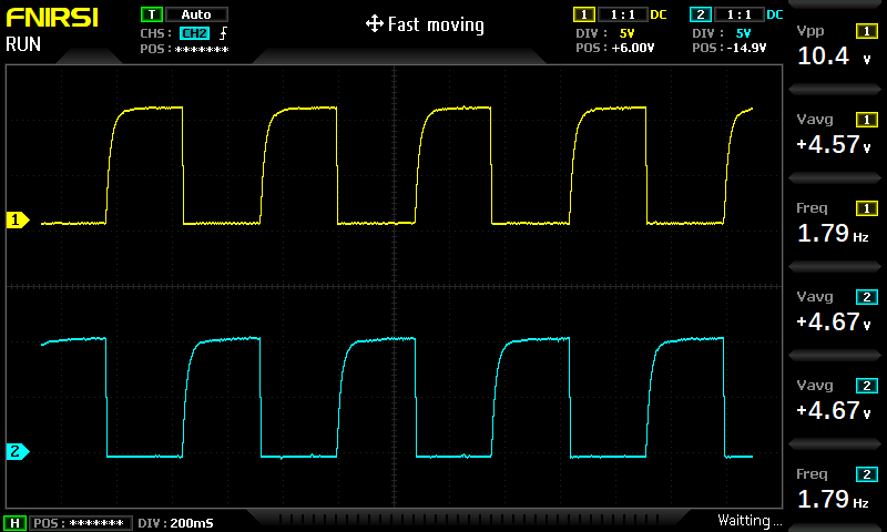
The picture shows two square waves, one yellow and one blue, representing the respective driving signals of the two LEDs.