How to Build a Wheeled Robot with Arduino
Description
Lesson dedicated to building a wheeled robot chassis with Arduino, ideal for robotic cars and obstacle-avoiding robots. We will see how to prepare the mounting spaces for Arduino, the L298N motor driver, a servomotor, two TT motors with wheels, and a front pivoting ball to ensure stability and smooth movement. A simple and practical project to learn how to create a compact, organized, and customizable robotic base, perfect for educational robotics experiments, Arduino kits, mobile robots, and DIY autonomous vehicles.
The robot is specifically designed to work with an ultrasonic sensor and/or a Bluetooth module, making it highly versatile and suitable for a wide range of projects and applications.
Required components:
- 1x Arduino UNO
- 1x HC-SR04 ultrasonic sensor
- 1x 5V Servomotor
- 1x L298N motor driver
- 1x Bluetooth module HC-05
- 2x 5/12V TT motor
- Jumper Cables (and optional breadboard)
3D Files:
Click here to download: Download_files
STEPS:
Step 1:
As a first step, it is necessary to 3D print all the parts of the project; the required files are in the 3D Files section above.
Next, take the base piece, turn it upside down, and insert the PLA ball into its designated housing. To make the insertion easier, you can use a hair dryer or a heat gun to slightly soften the plastic around the housing. However, be careful not to apply excessive heat, as the material could deform and compromise the correct operation of the component.
Once the ball has been inserted, check that the pivot joint can rotate freely on its own axis without experiencing excessive resistance or friction.
.jpeg)
Step 2:
After completing the first step, it is necessary to securely attach the mounting slots for the Arduino board, the L298N driver, and the servo motor.
Place the base back in its correct position and, using super glue or another suitable adhesive such as hot glue, firmly attach the mounts to the structure. Make sure to align them perfectly with the guide marks visible on the 3D-printed piece, ensuring a precise installation of the components.
Finally, wait until the glue has completely dried before proceeding with the next steps.
.jpeg)
Step 3:
Before proceeding with the final installation of all components on their respective mounts, it is necessary to create all the electrical connections between the Arduino board and the various modules, as well as the connections between the motor driver and the motors.
It is highly recommended to use soldering for all connections, since the robot will be moving and exposed to vibrations. Many connectors could accidentally disconnect during operation, causing malfunctions.
Additionally, for the power connections (GND and VCC) and the Bluetooth module connector, I chose to use a perfboard in order to keep the wiring more organized, stronger, and easier to manage.
Once all electrical connections have been completed as suggested in the
.jpeg)
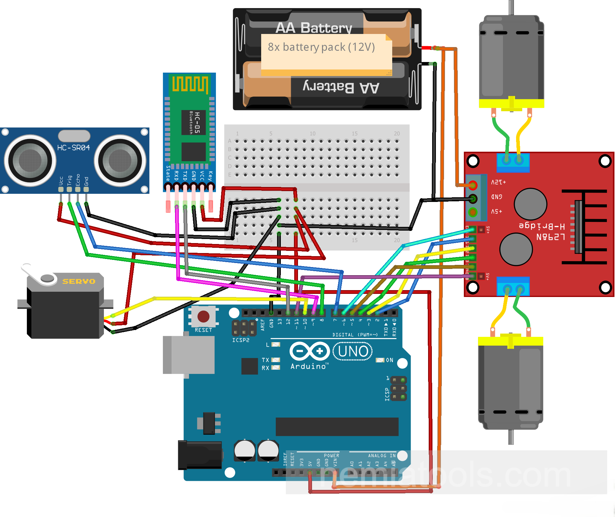 Suggested circuit scheme for this project
Step 4:
Once all the electronic board connections have been completed, proceed to install the TT motors underneath the robot chassis using the appropriate bolts.
Pay particular attention to the installation order, correctly positioning the motors on the right and left sides to ensure the proper orientation and operation of the robot's movement system.
.jpeg)
Step 5:
Now that the assembly is almost complete, the ultrasonic sensor module needs to be attached to the servo motor head. Before fixing it in place, make sure that the servo is positioned at 90 degrees, ensuring the correct alignment of the sensor during operation.
For the mounting, I used simple hot glue, which is a quick but not particularly professional solution. Alternatively, you can use a dedicated 3D-printed bracket, which provides a more precise and secure installation. Below, I will leave a Thingiverse link for downloading the bracket (the 3D project was not created by me).
3D Bracket: Download on Thingiverse
.jpeg)
Step 6:
As the final step, install the wheels onto the TT motors and attach a 12 V battery pack (for example, a holder for 8 AA batteries) to the robot chassis. It is recommended to use Velcro or another removable fastening method so that the Arduino USB port remains easily accessible for programming.
Also secure the Bluetooth module with Velcro in a stable location on the robot, such as above the Arduino connectors, allowing it to be removed easily whenever necessary.
In my build, I also added a diode to the power input connector to protect the circuit against reverse polarity, as well as a power switch to turn the robot on and off in a faster and more professional way.
At this point, your robot is finally complete! You can now move on to our tutorials, where this very robot is used in a variety of projects and practical demonstrations. You can find them directly in the sidebar next to this page or by visiting the Tutorials section of the website.
.jpeg)