Joystick-Controlled Servomotors
Description
This project is a dual-axis servo control system based on Arduino and a standard two-axis joystick module. The joystick provides two analog signals, one for the X axis and one for the Y axis, which are read by the Arduino and converted into servo angles from 0 to 180 degrees. In this way, moving the joystick left and right controls the horizontal servo, while moving it up and down controls the vertical servo. This simple and practical project is ideal for learning how to read analog joystick inputs, control servo motors, and create basic motion systems. It can be used as the base for a pan-tilt camera mount, robotic arm control, sensor positioning system, or any project that requires intuitive manual movement control.
Required components:
- 1x Arduino UNO
- 2x 5V Servomotor
- 1x 5v joystick module
- Jumper Cables (and optional breadboard)
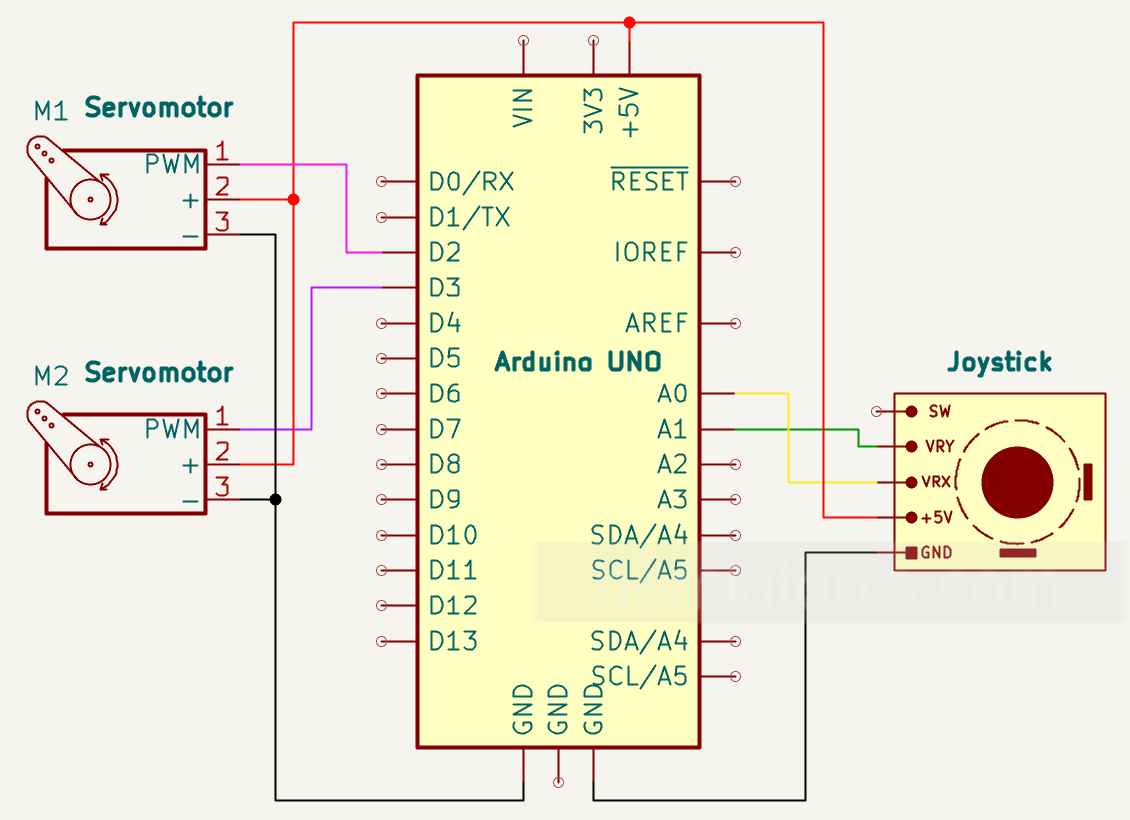
Schematic:
CODE:
// https://nemiatools.com

#include <Servo.h>  // Servo library

#define Horizontal_Servo_Pin 2   // Horizontal servo pin
#define Vertical_Servo_Pin  3    // Vertical servo pin
#define Horizontal_Pot_Pin A0    // Horizontal potentiometer pin
#define Vertical_Pot_Pin A1      // Vertical potentiometer pin

int Servo_Horizontal_Min = 0;    // Minimum angle for the horizontal servo
int Servo_Horizontal_Max = 180;  // Maximum angle for the horizontal servo
int Servo_Vertical_Min = 0;      // Minimum angle for the vertical servo
int Servo_Vertical_Max = 180;    // Maximum angle for the vertical servo

Servo Horizontal_Servo;   // Creates the horizontal servo object
Servo Vertical_Servo;     // Creates the vertical servo object

int Horizontal_Pot_Value;        // Stores the value read from the horizontal potentiometer
int Horizontal_Servo_Position;   // Stores the position of the horizontal servo
int Vertical_Pot_Value;          // Stores the value read from the vertical potentiometer
int Vertical_Servo_Position;     // Stores the position of the vertical servo

void setup()
{
  Horizontal_Servo.attach(Horizontal_Servo_Pin);  // Connects the horizontal servo to its pin
  Vertical_Servo.attach(Vertical_Servo_Pin);      // Connects the vertical servo to its pin
}

void loop()
{
  Horizontal_Pot_Value = analogRead(Horizontal_Pot_Pin);  // Reads the horizontal potentiometer value
  Vertical_Pot_Value = analogRead(Vertical_Pot_Pin);      // Reads the vertical potentiometer value

  Horizontal_Servo_Position = map(Horizontal_Pot_Value, 0, 1023, Servo_Horizontal_Min, Servo_Horizontal_Max);
  // Converts the horizontal potentiometer value into a servo angle

  Vertical_Servo_Position = map(Vertical_Pot_Value, 0, 1023, Servo_Vertical_Min, Servo_Vertical_Max);
  // Converts the vertical potentiometer value into a servo angle

  Horizontal_Servo.write(Horizontal_Servo_Position);  // Moves the horizontal servo to the calculated position
  Vertical_Servo.write(Vertical_Servo_Position);      // Moves the vertical servo to the calculated position

  delay(20);  // Small delay
}
How it works:
This project uses an Arduino to control two servo motors through a standard two-axis joystick module. The joystick provides two analog outputs: one for the horizontal axis and one for the vertical axis. These outputs are connected to the analog inputs A0 and A1 of the Arduino.
Inside the joystick module there are two variable resistive elements, one for each axis. When the joystick is moved left, right, up, or down, the voltage on the corresponding analog output changes. The Arduino reads these voltage levels using the analogRead() function, which converts them into values between 0 and 1023.
The horizontal joystick value is read from pin A0, while the vertical joystick value is read from pin A1. These values represent the current position of the joystick on each axis. When the joystick is centered, the values are usually around the middle of the range, approximately 512.
The Arduino then uses the map() function to convert the analog joystick values into servo angles. Since the servo motors move from 0 to 180 degrees, the input range from 0 to 1023 is converted into an output range from 0 to 180 degrees.
The horizontal servo is connected to digital pin 2 and is controlled by the horizontal movement of the joystick. Moving the joystick left or right changes the position of this servo. The vertical servo is connected to digital pin 3 and is controlled by the vertical movement of the joystick. Moving the joystick up or down changes the position of this servo.
After calculating the correct angle for each servo, the Arduino sends the position command using the Servo.write() function. This causes each servo motor to rotate to the angle that corresponds to the current joystick position.
The loop repeats continuously, so the servos follow the joystick movement in real time. A small delay of 20 milliseconds is added to make the movement smoother and to give the servos enough time to update their position.
This system creates an intuitive dual-axis control mechanism. It can be used for projects such as pan-tilt camera mounts, robotic arms, sensor positioning systems, or any application where two-direction manual movement control is needed.
For stable operation, it is recommended to power the servo motors with a suitable external power supply, especially when using larger servos. The grounds of the Arduino and the external power supply must be connected together.