Password door lock
Description
This project is an Arduino-based password control system using a 4x4 matrix keypad. The keypad allows the user to enter a numeric password, clear the input, and confirm the code using dedicated keys. When the correct password is entered and confirmed, the Arduino toggles the state of two digital outputs, which can be used to control LEDs, relays, buzzers, electronic locks, or other external devices through a suitable driver circuit. The project is useful for learning how matrix keypads work, how to read digital inputs, how to manage passwords in code, and how to simplify keypad handling using the Keypad.h library.
Required components:
- 1x Arduino UNO
- 1x Keypad module
- 1x 5V relay
- 2x 220kΩ resistor
- 1x BC547 (or any other suitable NPN)
- 1x Led
- Jumper cables (optional breadboard)
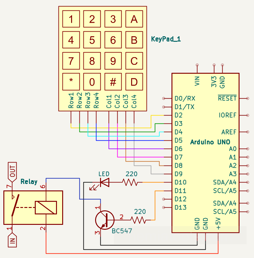
Schematic:
BASE CODE:
// https://nemiatools.com
#include <string.h> // string library used here to compare

const byte ROW_NUM = 4; // number of rows
const byte COLUMN_NUM = 4; // number of columns

char keys[ROW_NUM][COLUMN_NUM] = { // key layout
  {'1', '2', '3', 'A'}, // first row
  {'4', '5', '6', 'B'}, // second row
  {'7', '8', '9', 'C'}, // third row
  {'*', '0', '#', 'D'}  // fourth row
};

byte pin_rows[ROW_NUM] = {2, 3, 4, 5}; // row pins
byte pin_cols[COLUMN_NUM] = {6, 7, 8, 9}; // column pins

const String correctPassword = "1234"; // correct password
String inputPassword = ""; // entered password
bool outputState = false; // output state
bool clearNext = false; // clear after submit

void setup() {
  pinMode(10, OUTPUT); // pin 10 output
  pinMode(11, OUTPUT); // pin 11 output
  digitalWrite(10, LOW); // pin 10 off
  digitalWrite(11, LOW); // pin 11 off

  for (byte i = 0; i < ROW_NUM; i++) { // set rows
    pinMode(pin_rows[i], INPUT_PULLUP); // pull-up rows
  }

  for (byte i = 0; i < COLUMN_NUM; i++) { // set columns
    pinMode(pin_cols[i], OUTPUT); // output columns
    digitalWrite(pin_cols[i], HIGH); // columns off
  }
}

char getKey() { // read keypad

  for (byte col = 0; col < COLUMN_NUM; col++) { // scan columns

    for (byte i = 0; i < COLUMN_NUM; i++) { // all high
      digitalWrite(pin_cols[i], HIGH); // column off
    }

    digitalWrite(pin_cols[col], LOW); // current active

    for (byte row = 0; row < ROW_NUM; row++) { // scan rows
      if (digitalRead(pin_rows[row]) == LOW) { // key pressed
        return keys[row][col]; // return key
      }
    }
  }

  return 0; // no key pressed
}

void loop() {

  if (clearNext) { // reset requested
    inputPassword = ""; // clear password
    clearNext = false; // reset flag
  }

  char key = getKey(); // read key

  if (!key) { // no key pressed
    return; // exit immediately
  }

  delay(150); // debounce delay

  if (key == '*') { // clear input
    inputPassword = ""; // clear password
  }
  else if (key == '#') { // submit password
    if (inputPassword == correctPassword) { // correct password
      outputState = !outputState; // toggle state
      digitalWrite(10, outputState ? HIGH : LOW); // pin 10
      digitalWrite(11, outputState ? HIGH : LOW); // pin 11
    }
    clearNext = true; // clear input after submission
  }
  else if (key >= '0' && key <= '9') { // numbers only
    inputPassword += key; // add digit
  }

  while (getKey() != 0) { // wait release
    delay(10); // short wait
  }
}
CODE WITH Keypad.h:
// https://nemiatools.com
#include <Keypad.h> // Keypad library

const byte ROW_NUM = 4; // number of rows
const byte COLUMN_NUM = 4; // number of columns

char keys[ROW_NUM][COLUMN_NUM] = { // key layout
  {'1', '2', '3', 'A'}, // first row
  {'4', '5', '6', 'B'}, // second row
  {'7', '8', '9', 'C'}, // third row
  {'*', '0', '#', 'D'}  // fourth row
};

int pin_rows[ROW_NUM] = {2, 3, 4, 5}; // row pins
int pin_cols[COLUMN_NUM] = {6, 7, 8, 9}; // column pins

Keypad keypad = Keypad(makeKeymap(keys), pin_rows, pin_cols, ROW_NUM, COLUMN_NUM); // keypad object

const String correctPassword = "1234"; // correct password
String inputPassword = ""; // entered password
bool outputState = false; // output state
bool clearNext = false; // clear after submit

void setup() {
  pinMode(10, OUTPUT); // pin 10 output
  pinMode(11, OUTPUT); // pin 11 output
  digitalWrite(10, LOW); // pin 10 off
  digitalWrite(11, LOW); // pin 11 off
}

void loop() {

  if (clearNext) { // reset requested
    inputPassword = ""; // clear password
    clearNext = false; // reset flag
  }

  char key = keypad.getKey(); // read key

  if (!key) { // no key pressed
    return; // exit immediately and skip the rest of the code
  }

  delay(150); // debounce delay

  if (key == '*') { // clear input
    inputPassword = ""; // clear password
  }
  else if (key == '#') { // submit password
    if (inputPassword == correctPassword) { // correct password
      outputState = !outputState; // toggle state
      digitalWrite(10, outputState ? HIGH : LOW); // pin 10
      digitalWrite(11, outputState ? HIGH : LOW); // pin 11
    }
    clearNext = true; // clear input after submission
  }
  else if (key >= '0' && key <= '9') { // numbers only
    inputPassword += key; // add digit
  }
}
How it works:
This project uses an Arduino and a 4x4 matrix keypad to create a simple password-based control system. The keypad contains 16 keys arranged in 4 rows and 4 columns. Each key works by connecting one row to one column when it is pressed. Thanks to this matrix structure, the Arduino does not need one input pin for each key. Instead, it only needs 8 pins: 4 for the rows and 4 for the columns.
In the first version of the code, the keypad is read manually without using an external library. The number of rows and columns is defined with ROW_NUM and COLUMN_NUM, while the keys array contains the layout of the keypad. This array tells the Arduino which character corresponds to each row and column position, for example '1', '2', '3', 'A', and so on.
The row pins are defined with byte pin_rows[ROW_NUM] = {2, 3, 4, 5};, while the column pins are defined with byte pin_cols[COLUMN_NUM] = {6, 7, 8, 9};. Pins 10 and 11 are configured as outputs and are switched ON or OFF when the correct password is entered. These outputs can be connected to LEDs or, with a proper transistor, MOSFET, or relay module, to external loads such as locks or other devices.
The variable correctPassword stores the password that must be entered, in this case "1234". The variable inputPassword stores the digits pressed by the user. The variable outputState remembers whether the outputs are currently ON or OFF, while clearNext is used to clear the entered password after a submission.
In the setup() function of the manual version, the output pins 10 and 11 are set as outputs using pinMode(10, OUTPUT); and pinMode(11, OUTPUT);. They are initially turned OFF with digitalWrite(10, LOW); and digitalWrite(11, LOW);. The row pins are configured as pull-up inputs with pinMode(pin_rows[i], INPUT_PULLUP);. This is important because an Arduino input pin must always have a defined electrical state. If a pin is left floating, it may randomly read HIGH or LOW because of electrical noise. The internal pull-up resistor keeps each row normally HIGH when no key is pressed, without needing external resistors.
Because the rows use INPUT_PULLUP, the logic is inverted: an unpressed key reads HIGH, while a pressed key reads LOW. This happens because the columns are normally kept HIGH with digitalWrite(pin_cols[i], HIGH);, but during scanning the Arduino activates one column at a time by setting it LOW with digitalWrite(pin_cols[col], LOW);. If a key in that column is pressed, it connects the selected LOW column to one of the row pins, so the Arduino detects a LOW signal on that row.
The getKey() function performs the manual keypad scan. It checks each column one at a time. First, all columns are set HIGH, then the current column being tested is set LOW. After that, the Arduino reads all row pins using digitalRead(pin_rows[row]). If one row reads LOW, it means that the key at the intersection of that row and the active column is being pressed. The function then returns the corresponding character with return keys[row][col];. If no key is pressed, the function returns return 0;.
In the loop() function, the Arduino first checks if clearNext is true. If it is, the entered password is cleared with inputPassword = ""; and the flag is reset with clearNext = false;. Then the code calls char key = getKey(); to check whether a key has been pressed. If no key is detected, the condition if (!key) becomes true and the function exits immediately with return;, skipping the rest of the loop. This keeps the program simple and prevents unnecessary operations when the keypad is not being used.
When a key is detected, the code waits for 150 milliseconds using delay(150);. This delay is used for debounce. Mechanical buttons do not usually create a perfectly clean signal when pressed. For a very short time, the electrical contact can bounce, causing the Arduino to detect multiple rapid presses even though the user pressed the key only once. The debounce delay gives the signal time to stabilize before the program continues. This is a simple blocking debounce method, but it works well for basic keypad projects like this one.
After the debounce delay, the program checks which key was pressed. If the key is '*', the condition if (key == '*') is true and the password is cleared with inputPassword = "";. This allows the user to restart the password entry. If the key is '#', the condition else if (key == '#') is true and the password is submitted. The program compares the entered password with the correct one using if (inputPassword == correctPassword). If the two strings are equal, the password is correct and the output state is toggled.
The instruction outputState = !outputState; changes the output state from false to true or from true to false. This means that every time the correct password is entered, the outputs switch state: if they were OFF, they turn ON; if they were ON, they turn OFF.
The lines digitalWrite(10, outputState ? HIGH : LOW); and digitalWrite(11, outputState ? HIGH : LOW); use the ternary operator. The ternary operator is a compact way to write a simple if/else condition. In this case, outputState ? HIGH : LOW means: if outputState is true, use HIGH; otherwise, use LOW. So the pins are turned ON when outputState is true and turned OFF when outputState is false.
If the pressed key is a number between '0' and '9', the condition else if (key >= '0' && key <= '9') becomes true and the code adds that digit to the entered password using inputPassword += key;. This allows the password to be built one digit at a time. The keys A, B, C, and D are ignored in this project because only numeric input is accepted.
At the end of the manual code, the loop while (getKey() != 0) waits until the user releases the key. This prevents the same key press from being read many times while the button is still being held down. Inside this loop, a small delay of 10 milliseconds is used with delay(10); to avoid checking the keypad too aggressively.
The second version of the code uses the Keypad.h library, included with #include <Keypad.h>. This library simplifies the project because it handles most of the keypad scanning internally. Instead of manually setting rows as inputs, columns as outputs, activating one column at a time, and checking each row, the code creates a Keypad object using the keypad layout, the row pins, the column pins, and the keypad size.
The instruction Keypad keypad = Keypad(makeKeymap(keys), pin_rows, pin_cols, ROW_NUM, COLUMN_NUM); creates the keypad object. The makeKeymap(keys) part tells the library which character belongs to each physical key position. The pin_rows and pin_cols arrays tell the library how the keypad is connected to the Arduino.
Once the keypad object has been created, the program can simply call char key = keypad.getKey();. The function keypad.getKey() returns the character of the pressed key when a key press is detected. If no key is pressed, it returns no valid key. This makes the main loop much cleaner because the manual getKey() scanning function is no longer needed.
Using the Keypad.h library is convenient because it improves readability and reduces the chance of mistakes in the scanning code. It also makes the program easier to modify if a different keypad size is used, such as a 3x4 keypad instead of a 4x4 keypad. The library can also support more advanced keypad features, such as key states, hold detection, release detection, and multiple key handling, which are useful in more complex projects.
In this project, both versions of the code perform the same main function: the user enters a password using the keypad, presses '#' to confirm it, and presses '*' to clear the input. If the entered password matches the stored password, the Arduino toggles the outputs on pins 10 and 11.
When controlling loads such as relays, motors, solenoids, or electronic locks, the load should not be powered directly from the Arduino output pin. A transistor, MOSFET, relay module, or proper driver circuit should be used, and the Arduino ground must be connected to the external power supply ground when required.