How to Control an LED via Bluetooth with Arduino
Description
This project is an Arduino Bluetooth LED controller built with an Arduino board, a Bluetooth serial module, and an LED. The Bluetooth module receives commands from a smartphone, tablet, or computer and sends them to the Arduino through serial communication. When the Arduino receives the character “1”, it turns the LED on. When it receives the character “0”, it turns the LED off. This project is useful for learning wireless control, Bluetooth serial communication, SoftwareSerial, digital outputs, and basic remote control with Arduino.
Required components:
- 1x Arduino UNO
- 1x HC-05 bluetooth module
- 1x LED
- 1x 220Ω resistor
- Jumper Cables (and optional breadboard)
Schematic:
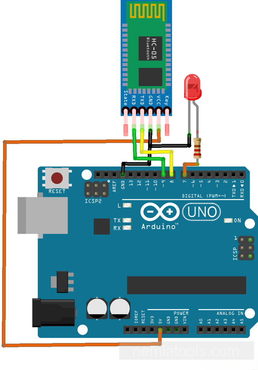
CODE:
// https://nemiatools.com
#include <SoftwareSerial.h> // Imports software serial library
SoftwareSerial bluetooth(8, 9); // Creates Bluetooth serial port

const int PIN_LED = 7; // Defines LED output pin
char command; // Stores received command
bool state = false; // Stores LED state

void setup() {
  pinMode(PIN_LED, OUTPUT); // Sets LED pin output
  bluetooth.begin(9600); // Starts Bluetooth communication
  Serial.begin(9600); // Starts serial monitor
}

void loop() {
  if (bluetooth.available()) { // Checks Bluetooth data availability
    command = bluetooth.read(); // Reads Bluetooth command
    Serial.print(command); // Prints received command
  } // Ends availability check

  if(command == '0') state = false; // Turns LED state off
  else if(command == '1') state = true; // Turns LED state on

  if(state) digitalWrite(PIN_LED, HIGH); // Turns LED on
  else digitalWrite(PIN_LED, LOW); // Turns LED off
}
How it works:
This project allows an Arduino to control an LED using Bluetooth commands. A Bluetooth module, such as an HC-05 or HC-06, receives characters from an external device and sends them to the Arduino.
The line #include <SoftwareSerial.h> adds the SoftwareSerial library. This library allows the Arduino to create an additional serial communication port using normal digital pins, instead of using only the hardware serial pins 0 and 1.
The line SoftwareSerial bluetooth(8, 9); creates a software serial port called bluetooth. In this instruction, pin 8 works as RX, so it receives data from the Bluetooth module TX pin, while pin 9 works as TX, so it can send data to the Bluetooth module RX pin.
The line const int PIN_LED = 7; defines pin 7 as the LED output pin. The LED is turned on or off according to the Bluetooth command received by the Arduino.
The variable char command; stores the character received from the Bluetooth module. The variable bool state = false; stores the LED state. At the beginning, it is false, so the LED starts turned off.
Inside setup(), the line pinMode(PIN_LED, OUTPUT); configures the LED pin as an output. This allows the Arduino to send HIGH or LOW signals to the LED.
The line bluetooth.begin(9600); starts Bluetooth serial communication at 9600 baud. This speed must match the baud rate of the Bluetooth module.
The line Serial.begin(9600); starts the normal Arduino serial communication with the computer. In this project, it is used mainly for testing, because the received Bluetooth command is also printed on the Serial Monitor.
Inside loop(), the condition if (bluetooth.available()) checks if a new character has arrived from the Bluetooth module. If data is available, the line command = bluetooth.read(); reads one character and stores it in the variable command.
The line Serial.print(command); prints the received command on the Serial Monitor. This is useful to verify that the Arduino is really receiving the characters sent through Bluetooth.
The condition if(command == '0') state = false; checks if the received command is the character 0. If it is, the LED state becomes false, meaning that the LED must be turned off.
The condition else if(command == '1') state = true; checks if the received command is the character 1. If it is, the LED state becomes true, meaning that the LED must be turned on.
The final part of the loop applies the saved state to the LED. If state is true, the line digitalWrite(PIN_LED, HIGH); turns the LED on. Otherwise, digitalWrite(PIN_LED, LOW); turns it off.
The important idea is that the LED does not turn on only for a moment. The variable state memorizes the last valid command. After receiving '1', the LED stays on until a '0' command is received.
Overall, the Bluetooth module works like a wireless serial cable. The external device sends simple characters, the Arduino reads them, updates the LED state, and controls the output pin accordingly.
For real hardware, connect the Bluetooth module TX pin to Arduino pin 8, the Bluetooth module RX pin to Arduino pin 9, and connect GND together. If the Bluetooth module RX pin is not 5V tolerant, use a voltage divider or level shifter between Arduino TX and the module RX pin.