Termometer with LCD display
Description
This project is a digital temperature measurement system built around an Arduino board, an I2C LCD display, and an analog temperature sensor connected to pin A0. The circuit reads the sensor value continuously, converts it into a temperature value in degrees Celsius, and shows the result on a 16x2 LCD screen together with a custom degree symbol. The project also includes an initial welcome screen displaying “TERMOMETER” and “by Nemiatools” before switching to real-time temperature monitoring. With its simple structure and clear output, it is an excellent project for learning the basics of analog sensors, LCD displays, custom characters, and Arduino-based environmental monitoring. It can be used as a foundation for digital thermometers, weather stations, room monitoring systems, or other temperature-based electronic applications.
Required components:
- 1x Arduino UNO
- 1x LCD display with integrated I2C module
- 1x TMP36 temperature sensor (or other compatible ones)
- Jumper Cables (and optional breadboard)
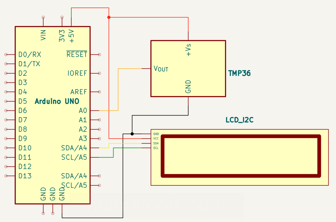
Schematic:
CODE:
// https://nemiatools.com
#include <Wire.h> // Include I2C communication library
#include  <LiquidCrystal_I2C.h> // LCD library

LiquidCrystal_I2C lcd_1(0x27, 16, 2); // LCD object

byte degree_symbol[8] = { // Degree symbol
  B00110, // Row 1
  B01001, // Row 2
  B01001, // Row 3
  B00110, // Row 4
  B00000, // Row 5
  B00000, // Row 6
  B00000, // Row 7
  B00000  // Row 8
};

void setup()
{
  lcd_1.init(); // Initialize LCD
  pinMode(A0, INPUT); // Temperature sensor input

  lcd_1.backlight(); // Enable backlight
  lcd_1.createChar(0, degree_symbol); // Create symbol
  lcd_1.setCursor(3, 0); // First line
  lcd_1.print("TERMOMETER"); // Show title
  lcd_1.setCursor(2, 1); // Second line
  lcd_1.print("by Nemiatools"); // Show author
  delay(3000); // 3 seconds for the home screen
  lcd_1.clear(); // Clear display
  lcd_1.setCursor(0, 0); // First line
  lcd_1.print("Temperature:"); // Static text
  lcd_1.setCursor(10, 1); // Degree symbol position
  lcd_1.write(byte(0)); // Print symbol
  lcd_1.setCursor(11, 1); // Unit position
  lcd_1.print("C"); // Celsius unit
}

void loop()
{
  lcd_1.setCursor(3, 1); // Temperature value position
  lcd_1.print((-40 + 0.488155 * (analogRead(A0) - 20))); // Calculate temperature and write it
  delay(10); // Small delay
}
How it works:
This project uses an Arduino board to read the temperature from an analog temperature sensor connected to pin A0 and display the result on a 16x2 LCD screen with an I2C interface.
The first important line is #include <LiquidCrystal_I2C.h>. This library allows the Arduino to communicate with an LCD display that uses an I2C adapter. A standard LCD without an I2C interface usually requires many digital pins to control the display, such as RS, E, D4, D5, D6, and D7. With the I2C interface, only two communication pins are needed: SDA and SCL. This makes the wiring much simpler, saves Arduino pins, and makes the circuit cleaner and easier to build.
The line LiquidCrystal_I2C lcd_1(0x27, 16, 2); creates the LCD object. The value 0x27 is the I2C address of the display module. This address is used by the Arduino to identify the LCD on the I2C bus. The values 16 and 2 indicate that the display has 16 columns and 2 rows.
The code then defines a custom degree symbol using the array byte degree_symbol[8]. Each row of this array represents one line of pixels inside a custom LCD character. This custom character is later used to display the degree symbol before the letter C, making the temperature reading look more professional and easier to understand.
Inside the setup() function, the line lcd_1.init(); initializes the LCD display and prepares it to receive commands from the Arduino through the I2C interface. The line pinMode(A0, INPUT); sets analog pin A0 as an input, because this pin receives the voltage signal from the temperature sensor.
The line lcd_1.backlight(); turns on the LCD backlight, so the text can be clearly visible. Then lcd_1.createChar(0, degree_symbol); stores the custom degree symbol in the LCD memory at position 0. This allows the symbol to be printed later using lcd_1.write(byte(0));.
The lines lcd_1.setCursor(3, 0); and lcd_1.print("TERMOMETER"); place the cursor on the first row and print the title of the project. Then lcd_1.setCursor(2, 1); and lcd_1.print("by Nemiatools"); print the author text on the second row. This creates an initial welcome screen when the circuit starts.
The line delay(3000); keeps the welcome screen visible for 3 seconds. After that, lcd_1.clear(); removes the initial text from the display and prepares the LCD for the real temperature reading screen.
The line lcd_1.setCursor(0, 0); moves the cursor to the beginning of the first row, and lcd_1.print("Temperature:"); prints the label that describes the measured value. Then the code places the degree symbol and the Celsius letter on the second row using lcd_1.setCursor(10, 1);, lcd_1.write(byte(0));, lcd_1.setCursor(11, 1);, and lcd_1.print("C");.
Inside the loop() function, the Arduino continuously updates the temperature value. The line lcd_1.setCursor(3, 1); places the cursor on the second row, where the numeric temperature value will be printed.
The most important line for the measurement is lcd_1.print((-40 + 0.488155 * (analogRead(A0) - 20)));. The function analogRead(A0) reads the voltage coming from the temperature sensor and converts it into a digital value between 0 and 1023. This happens because the Arduino analog-to-digital converter represents the input voltage as a number in that range.
The formula -40 + 0.488155 * (analogRead(A0) - 20) converts the raw analog value into degrees Celsius. The value 20 acts as an offset, meaning that the calculation starts from a reference point instead of directly from zero. The value 0.488155 represents the approximate temperature change for each analog reading step. In other words, every increase of one unit in the analog reading corresponds to about 0.488 degrees Celsius. Finally, -40 shifts the result so that the output matches the temperature scale expected from the sensor.
This type of formula is commonly used with analog temperature sensors in Arduino simulations and projects, where the sensor output voltage changes according to the measured temperature. The Arduino reads this voltage, converts it into a number, and then the formula transforms that number into a human-readable Celsius temperature.
The line delay(10); adds a very small pause between readings. Since the loop repeats continuously, the LCD is updated very quickly, giving the impression of real-time temperature monitoring.
Overall, the system works by reading an analog temperature signal, converting it into a Celsius value, and displaying it on an I2C LCD screen. Thanks to the I2C interface, the display requires fewer Arduino pins, the wiring is simpler, and the project remains easy to expand with other sensors or modules.
For correct operation, make sure the LCD I2C address matches the address used in the code. Many LCD I2C modules use 0x27, but some may use 0x3F. If the display does not show text, checking the I2C address is one of the first troubleshooting steps.