Adjustable Frequency with NE555
Description
This project is an adjustable frequency generator based on the popular NE555 timer IC. The circuit operates in astable mode, continuously generating a square-wave signal whose frequency can be easily adjusted through a potentiometer. Thanks to its simple design and low component count, it is an excellent project for learning the fundamentals of oscillators and timing circuits. The generated signal can be used for testing electronic circuits, creating clock pulses, driving LEDs, producing audio tones, or supporting various laboratory experiments.
Required components:
- 1x NE555
- 1x 1M Potentiometer
- 1x 1K Resistor
- 2x 10nF Ceramic Capacitor
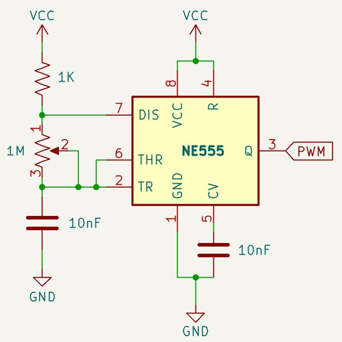
Schematic:
How it works:
The circuit uses the NE555 timer in astable mode, meaning the IC never remains fixed in one state, but continuously switches between a high and a low output. As a result, a square-wave signal is generated on pin 3, labeled as PWM in the schematic.
The operation is based on the charging and discharging of the capacitor connected to pins 2 and 6 of the NE555. These two pins monitor the voltage across the capacitor and allow the IC to determine when to change state.
During operation, the capacitor continuously charges and discharges between two internal threshold levels of the NE555: approximately 1/3 of VCC and 2/3 of VCC. When the capacitor voltage is low, the 555 drives the output high. When the voltage reaches the upper threshold, the 555 drives the output low and activates the internal discharge transistor connected to pin 7.
During the charging phase, the capacitor charges from about 1/3 VCC up to about 2/3 VCC. The current flows from VCC, through the fixed 1 kΩ resistor, then through the potentiometer, and finally into the capacitor. In this phase, pin 7 does not discharge the capacitor because the NE555’s internal discharge transistor is turned off. Therefore, the output on pin 3 remains high.
When the capacitor voltage reaches approximately 2/3 VCC, the internal comparator of the 555 changes state. At this point, the output goes low and the internal transistor connected to pin 7 turns on. Pin 7 is then pulled close to ground, allowing the capacitor to discharge through the potentiometer and the internal transistor of the 555.
During the discharge phase, the voltage across the capacitor drops to approximately 1/3 VCC. When this level is reached, the 555 changes state again: the output returns high, the discharge transistor turns off, and the capacitor starts charging once more. This cycle repeats continuously, generating a periodic output signal.
The potentiometer adjusts the frequency by changing the resistance through which the capacitor charges and discharges. Increasing the resistance makes the capacitor take longer to reach the internal thresholds of the 555, which lowers the frequency. Decreasing the resistance allows the capacitor to charge and discharge more quickly, increasing the frequency.
The operating voltage range of the NE555 is from 5 to 15 volts and its maximum output current reaches up to 200mA so for heavy loads it is recommended to use a MOSFET to control these.
Frequency formula:
\( f = \frac{1.44}{(R_1 + 2R_2) \cdot C} \)
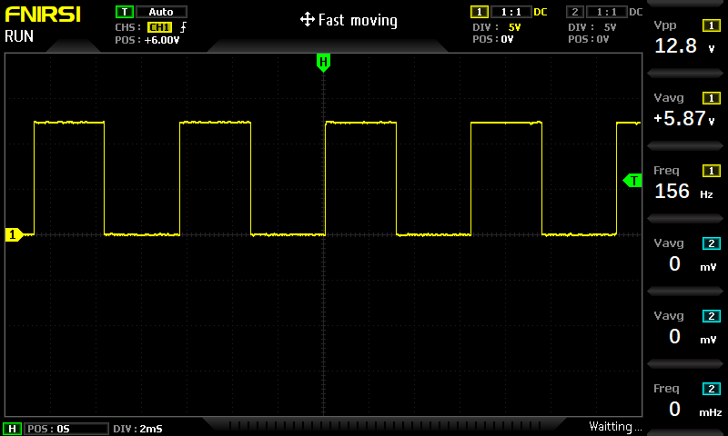
In This project \(R_1\) is the 1kΩ resistor and \(R_2\) is the 1MΩ potentiometerSquare wave image: