NE555 Clap Switch
Description
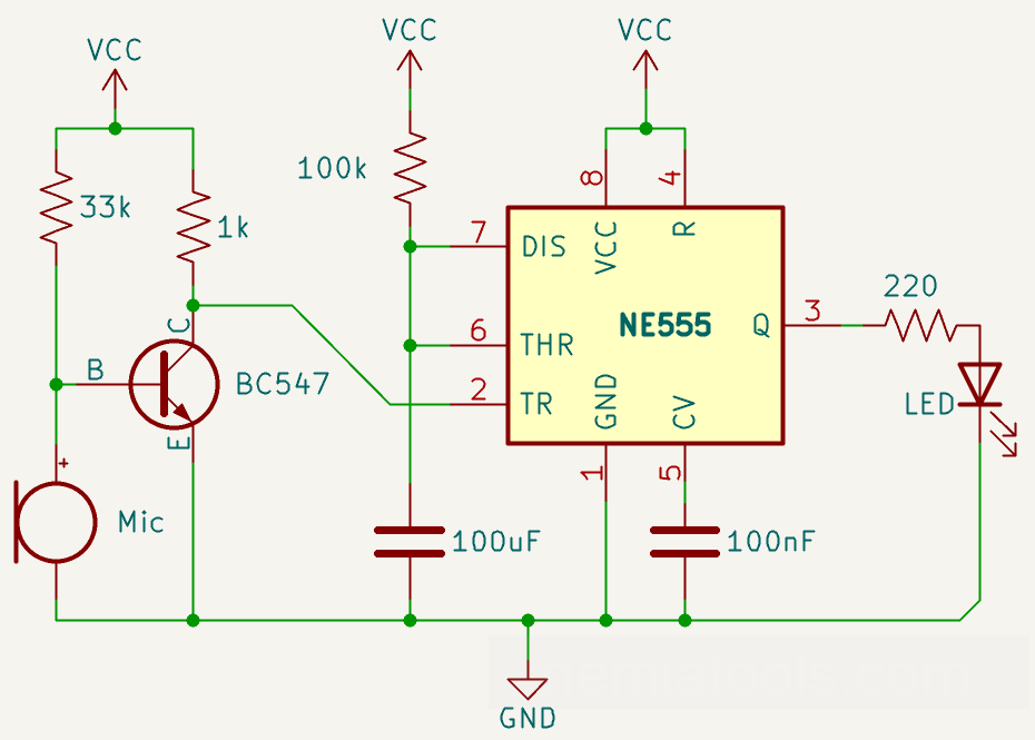
This project is a clap-activated timed light built around a condenser microphone, a BC547 transistor, an NE555 timer, and an LED. The microphone detects a clap, the transistor converts the weak audio signal into a suitable trigger pulse, and the NE555 keeps the LED switched on for a fixed period of approximately 11 seconds before turning it off automatically. The circuit is an excellent introduction to sound detection, transistor switching, active-low signals, RC timing, and the monostable operating mode of the NE555.
Required components:
- 1x NE555
- 1x 100nF ceramic capacitor
- 1x 100uF electrolytic capacitor
- 1x BC547 NPN transistor
- 1x Condenser microphone
- 1x 1kΩ resistor
- 1x 100kΩ resistor
- 1x 33kΩ resistor
- 1x 220Ω resistor
- 1x LED
Schematic:
How it works:
This circuit works as a sound-activated timer. A clap is detected by the microphone and converted into a short electrical pulse. The NE555 receives this pulse, switches the LED on, keeps it illuminated for a predetermined time, and then switches it off automatically.
The input stage consists of the condenser microphone, the 33k resistor, the BC547 transistor, and the 1k collector resistor. Its purpose is to detect the very small signal produced by the microphone and transform it into a clear trigger signal for the timer.
The condenser microphone is a polarized component containing a small internal transistor. The 33k resistor supplies the microphone with the bias current it needs to operate and also establishes the operating condition of the BC547 base.
When the environment is quiet, the microphone produces only small voltage variations. When a clap occurs, the sudden sound pressure creates a rapid variation in the microphone output voltage. A sufficiently strong positive variation increases the current entering the base of the BC547.
The BC547 is an NPN transistor connected in a common-emitter configuration. Its emitter is connected to ground, while its collector is connected to VCC through the 1k resistor. This resistor acts as the collector load and keeps the collector voltage HIGH when the transistor is not conducting.
When the clap drives the BC547 into conduction, current flows from VCC through the 1k resistor, through the collector-emitter path, and toward ground. As a result, the collector voltage rapidly falls from HIGH to LOW.
This inversion is important because pin 2, TRIGGER, of the NE555 is active LOW. Therefore, the transistor converts the microphone signal into the short negative pulse required to activate the timer.
The NE555 is configured in monostable mode. This means that it normally remains in one stable state, with its output LOW, and produces one temporary HIGH pulse whenever it receives a valid trigger.
The NE555 is powered through pin 8, VCC, and pin 1, GND. The RESET pin 4 is connected directly to VCC so that the timer remains permanently enabled. If pin 4 were pulled LOW, the output would be forced off regardless of the other signals.
Inside the NE555 there are three equal internal resistors that create two reference voltages: approximately 1/3 of VCC and 2/3 of VCC. Two internal comparators use these levels to control an internal memory latch.
In the resting condition, the output at pin 3 is LOW, the LED is off, and the internal discharge transistor connected to pin 7 keeps the 100uF timing capacitor discharged close to zero volts.
When a clap makes pin 2 fall below approximately 1/3 of VCC, the trigger comparator sets the internal latch. The output at pin 3 immediately becomes HIGH and the internal discharge transistor at pin 7 switches off.
With the discharge transistor off, the 100uF capacitor begins charging from VCC through the 100k resistor. The voltage across the capacitor rises gradually rather than instantly because the resistor limits the charging current.
The capacitor voltage is monitored by pin 6, THRESHOLD. When this voltage reaches approximately 2/3 of VCC, the threshold comparator resets the internal latch.
At that moment, the output at pin 3 returns LOW, the LED turns off, and the internal transistor connected to pin 7 switches on again. Pin 7 then provides a low-resistance path to ground, rapidly discharging the timing capacitor and preparing the circuit for the next clap.
The duration of the output pulse is determined mainly by the 100k timing resistor and the 100uF timing capacitor, according to the NE555 monostable formula.
With the values used in this circuit the formula gives approximately 11 seconds. Therefore, after a valid clap, the LED should remain illuminated for about 11 seconds.
The real duration may be slightly different because electrolytic capacitors such as the 100uF capacitor normally have relatively wide tolerances and may also be affected by leakage current, temperature, and component quality.
The output from pin 3 passes through the 220 ohm resistor before reaching the LED. This resistor limits the LED current and protects both the LED and the NE555 output stage.
The 100nF capacitor connected between pin 5, CONTROL VOLTAGE, and ground is not part of the 11-second timing network. Its purpose is to filter electrical noise from the internal reference voltage, reducing false switching and improving timer stability.
The complete signal path is therefore: the microphone detects the clap, the BC547 amplifies and inverts the signal, pin 2 triggers the NE555, the output activates the LED, and the 100k–100uF network determines how long the LED remains on.
This circuit does not memorize an ON or OFF state. Every valid clap starts a temporary timing cycle, and the LED switches off automatically when that cycle ends.
Because the microphone stage is very simple, its sensitivity can depend strongly on the supply voltage, microphone model, surrounding noise, and component tolerances. For more reliable operation, a sensitivity adjustment or a comparator with hysteresis could be added. A 100nF supply-decoupling capacitor placed close to pins 8 and 1 of the NE555 is also recommended.
Time formula:
\( t = 1,1 × R × C \)
In This project \(R\) is the 100kΩ resistor and \(C\) is the 100uF electrolytic capacitorFuture developments:
The circuit could be converted from a timed clap detector into a true clap-controlled switch by connecting its clean output pulse to a T-latch. A T-latch changes its output state every time it receives a valid pulse: the first clap would switch the output ON, while the second clap would switch it OFF. A D-type flip-flop such as a CD4013 can be configured as a toggle by connecting its inverted output back to its D input. The latch output could then control a relay through a transistor or MOSFET driver, allowing the first clap to energize the relay and the next clap to release it. The relay would therefore remain in its current state indefinitely instead of switching off automatically after approximately 11 seconds. A flyback diode should be connected across the relay coil, and the NE555 pulse should be kept short enough to guarantee only one toggle for each clap.