Motor driven by NE555
Description
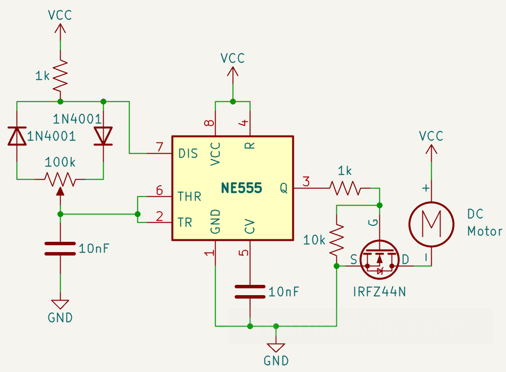
This project is a PWM DC motor speed controller built around an NE555 timer, a 100k potentiometer, two 1N4001 diodes, an IRFZ44N MOSFET, and a DC motor. The circuit generates an adjustable PWM signal, allowing the motor speed to be controlled by changing the duty cycle instead of simply reducing the supply voltage. The potentiometer and the two diodes make it possible to separately control the charging and discharging time of the timing capacitor, while the MOSFET acts as a power switch for the motor. This project is an excellent introduction to analog PWM generation, 555 timer circuits, MOSFET switching, and DC motor speed control. It can be used as a foundation for fan controllers, small robotic vehicles, variable-speed pumps, model motors, or other low-voltage DC motor applications.
Required components:
- 1x NE555
- 2x 1kΩ Resistor
- 1x 10kΩ Resistor
- 2x 10nF ceramic capacitor
- 1x 100kΩ Potentiometer
- 2x 1N4001 Diode (or any other suitable diode)
- 1x MOSFET n-channel IRFZ44N
- 1x DC Motor
Schematic:
How it works:
This project uses an NE555 timer to generate a PWM signal that controls the speed of a DC motor. PWM means Pulse Width Modulation. Instead of changing the motor voltage in a linear way, the circuit switches the motor ON and OFF very quickly. If the ON time is longer, the motor receives more average power and spins faster. If the OFF time is longer, the motor receives less average power and spins slower.
The NE555 is powered through pin 8 (VCC) and pin 1 (GND). Pin 8 is connected to the positive supply, while pin 1 is connected to ground. The reset pin, pin 4, is also connected to VCC. This keeps the NE555 permanently enabled, so it can continuously generate the PWM signal.
The control voltage pin, pin 5, is connected to ground through a 10nF capacitor. This capacitor is not the timing capacitor. Its purpose is to filter electrical noise on the internal reference voltage of the NE555. This makes the timer more stable and helps prevent unwanted changes in the PWM signal.
The timing section of the circuit is built around the 100k potentiometer, the two 1N4001 diodes, the 1k resistor, and the left 10nF timing capacitor. The timing capacitor is connected to the NE555 trigger and threshold pins, which are pin 2 (TR) and pin 6 (THR). These two pins monitor the voltage across the capacitor.
Inside the NE555 there are two voltage thresholds. When the capacitor voltage falls below about 1/3 of VCC, the trigger input activates the timer and the output goes HIGH. When the capacitor voltage rises above about 2/3 of VCC, the threshold input resets the timer and the output goes LOW. This continuous charging and discharging of the capacitor creates the PWM waveform.
The discharge pin, pin 7, is connected to the timing network. Inside the NE555, this pin is connected to an internal transistor. When the output is LOW, the discharge transistor turns ON and connects pin 7 to ground. When the output is HIGH, the discharge transistor turns OFF, allowing the timing capacitor to charge again.
The 100k potentiometer is the main speed control element. It is not used simply as a voltage divider. In this circuit, it works as two variable resistances: one part of the potentiometer controls the capacitor charging time, and the other part controls the capacitor discharging time. The wiper of the potentiometer is connected to the timing capacitor and to pins 2 and 6 of the NE555.
The two 1N4001 diodes are very important because they separate the charging path from the discharging path. During the charging phase, current flows from VCC through the 1k resistor, through one diode, through one side of the potentiometer, and then into the timing capacitor. The other diode is reverse-biased, so it does not conduct during this phase.
During the discharging phase, the opposite happens. The timing capacitor discharges through the other side of the potentiometer, through the other diode, and into pin 7 of the NE555, where the internal discharge transistor pulls the current to ground. In this phase, the first diode is reverse-biased and does not conduct.
This diode arrangement is what makes the circuit a good PWM controller. By turning the potentiometer, one resistance becomes smaller while the other becomes larger. As a result, the capacitor may charge quickly and discharge slowly, or charge slowly and discharge quickly. This changes the ratio between ON time and OFF time, which is the duty cycle of the PWM signal.
Without the two diodes, a standard NE555 astable circuit usually charges and discharges the capacitor through paths that are not fully independent. This makes the duty cycle harder to control and often prevents the circuit from reaching a wide adjustment range. With the two diodes, the charge and discharge paths are separated, giving smoother and more effective motor speed control.
The 1k resistor near the timing network limits current through the diodes, the potentiometer, and the NE555 discharge transistor. This is especially important when the potentiometer is turned close to one of its extreme positions, where one part of the resistance can become very small.
The PWM output is taken from pin 3 of the NE555. This pin produces a square wave that switches between LOW and HIGH. The output signal goes through a 1k resistor before reaching the gate of the IRFZ44N MOSFET. This resistor limits the gate charging current and helps make the switching more stable.
The 10k resistor connected between the MOSFET gate and ground works as a pull-down resistor. Its job is to keep the MOSFET turned OFF when the NE555 output is not actively driving the gate, for example during startup or unstable conditions. Without this resistor, the MOSFET gate could float and the motor might turn on unexpectedly.
The IRFZ44N is used as a low-side electronic switch. The motor positive terminal is connected to VCC, while the motor negative terminal is connected to the MOSFET drain. The MOSFET source is connected to ground. When the NE555 output is HIGH, the MOSFET turns ON and current flows from VCC, through the motor, through the MOSFET, and finally to ground. When the NE555 output is LOW, the MOSFET turns OFF and the motor current is interrupted.
Because this switching happens very quickly, the motor does not simply stop and start visibly at every pulse. Instead, it responds to the average power delivered by the PWM signal. A higher duty cycle means the motor is ON for a larger part of each cycle, so it spins faster. A lower duty cycle means the motor is ON for a smaller part of each cycle, so it spins slower.
Overall, the circuit works by using the NE555 to create an adjustable PWM signal, the potentiometer and diodes to control the duty cycle, and the MOSFET to switch the motor current efficiently. This allows the motor speed to be controlled with much better efficiency than using a simple series resistor, because the MOSFET mainly operates as an ON/OFF switch rather than wasting power as heat.
For real hardware use, it is recommended to add a flyback diode or another protection device across the motor to protect the MOSFET from voltage spikes generated by the motor coil. Also make sure the power supply can provide enough current for the motor, the grounds are correctly connected, and the MOSFET receives enough gate voltage to turn on properly.
Duty Cycle formula:
\( D(\%) = \frac{R_1 + R_2}{R_1 + 2R_2}\cdot 100 \)
In This project \(R_1\) is the 1kΩ resistor and \(R_2\) is the 100kΩ potentiometer