Simple paino with NE555
Description
This project is a simple electronic piano based on the popular NE555 timer IC. The circuit operates in astable mode and generates different audio tones by selecting different resistor values through push buttons, each corresponding to a musical note. The output signal drives a buzzer, allowing the circuit to produce basic melodies in a very simple way. Thanks to its low component count and easy-to-understand design, this project is ideal for learning the basics of oscillators, frequency generation, and sound production with the NE555 timer.
Required components:
- 1x NE555
- 1x 1K Resistor
- 2x 10nF Ceramic Capacitor
- 1x Buzzer
- 1x 270kΩ resistor
- 1x 240kΩ resistor
- 1x 220kΩ resistor
- 1x 200kΩ resistor
- 1x 180kΩ resistor
- 1x 160kΩ resistor
- 1x 145kΩ resistor
Schematic:
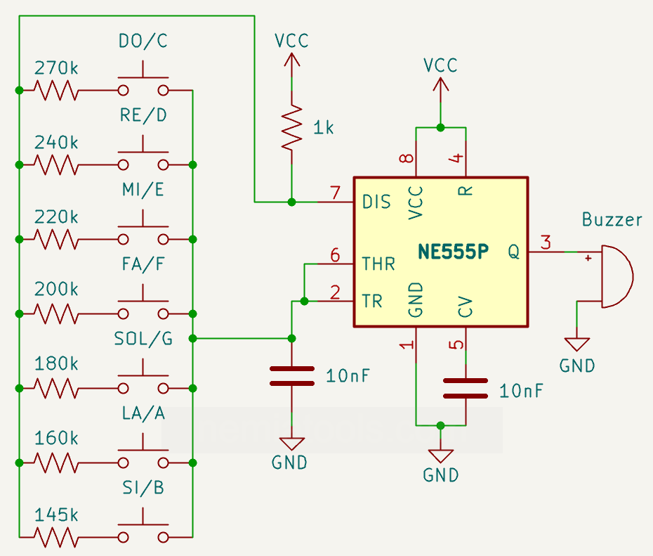
How it works:
This circuit uses the NE555 timer in astable mode to generate audio-frequency square waves. The output signal is produced on pin 3 of the NE555 and is sent to the buzzer, which converts the electrical signal into sound.
The operation is based on the charging and discharging of the capacitor connected to pins 2 and 6 of the NE555. These two pins monitor the voltage across the capacitor and allow the IC to decide when to switch the output state.
During operation, the capacitor continuously charges and discharges between two internal threshold levels of the NE555: approximately 1/3 of VCC and 2/3 of VCC. When the capacitor voltage is low, the output on pin 3 goes high. When the capacitor voltage reaches the upper threshold, the output goes low and the internal discharge transistor connected to pin 7 turns on.
Each push button selects a different resistor value connected to the timing capacitor. These resistors determine how fast the capacitor charges and discharges. Since each resistor has a different value, each button produces a different oscillation frequency, corresponding to a musical note such as DO/C, RE/D, MI/E, FA/F, SOL/G, LA/A, and SI/B.
When a button is pressed, the capacitor charges through the 1 kΩ resistor and the selected note resistor. A higher resistor value makes the capacitor charge more slowly, producing a lower-frequency tone. A lower resistor value allows the capacitor to charge and discharge more quickly, producing a higher-frequency tone.
When the capacitor voltage reaches about 2/3 of VCC, the NE555 changes state: the output goes low and pin 7 is internally connected to ground. The capacitor then discharges through the selected note resistor and the internal discharge transistor of the NE555.
Once the capacitor voltage drops to about 1/3 of VCC, the NE555 switches state again. The output returns high, the discharge transistor turns off, and the capacitor starts charging again. This cycle repeats continuously as long as a button is pressed, generating the square wave that drives the buzzer.
The different resistor values are chosen to approximate the frequencies of musical notes. Pressing different buttons changes the timing resistance, and therefore changes the sound frequency produced by the buzzer. When no button is pressed, the timing path is open, so the oscillator does not generate a tone.
The 10 nF capacitor connected to pin 5 helps stabilize the internal reference voltage of the NE555, while pin 4 is connected to VCC to keep the timer enabled.
The NE555 typically operates from about 5 to 15 volts and can drive small loads directly from its output. For larger speakers or higher-current loads, it is recommended to use a transistor or MOSFET driver instead of connecting the load directly to pin 3.
Frequency formula:
\( f = \frac{1.44}{(R_1 + 2R_2) \cdot C} \)
In This project \(R_1\) is the 1kΩ resistor and \(R_2\) are all the different resistors after the buttons